

The Smith chart from electrical engineering is the picture of a Cartesian grid beneath the perform
f(z) = (z − 1)/(z + 1).
Extra particularly, it’s the picture of a grid in the suitable half-plane.
This submit will derive the essential mathematical properties of this graph however won’t go into the purposes. Stated one other approach, I’ll clarify the way to make a Smith chart, not the way to use one.
We’ll use z to indicate factors in the suitable half-plane and w to indicate the picture of those factors beneath f. We’ll converse of strains within the z airplane and the circles they correspond to within the w airplane.
Möbius transformations
Our perform f is a particular case of a Möbius transformation. There’s a theorem that claims Möbius transformation map generalized circles to generalized circles. Right here a generalized circle means a circle or a line; you’ll be able to consider a line as a circle with infinite radius. We’re going to get loads of mileage out of that theorem.
Picture of the imaginary axis
The perform f maps the imaginary axis within the z airplane to the unit circle within the w airplane. We are able to show this utilizing the theory above. The imaginary axis is a line, so it’s picture is both a line or a circle. We are able to take three factors on the imaginary axis within the z airplane and see the place they go.
Once we decide z equal to 0, i, and −i from the imaginary axis we get w values of −1, i, and −i. These three w values don’t line on a line, so the picture of the imaginary axis have to be a circle. Moreover, three factors uniquely decide a circle, so the picture of the imaginary axis is the circle containing −1, i, and −i, i.e. the unit circle.
Picture of the suitable half-plane
The imaginary axis is the boundary of the suitable half-plane. Since it’s mapped to the unit circle, the suitable half-plane is both mapped to the inside of the unit circle or the outside of the unit circle. The purpose z = 1 goes to w = 0, and so the suitable half-plane is mapped contained in the unit circle.
Pictures of vertical strains
Let’s take into consideration what occurs to vertical strains within the z airplane, strains with fixed constructive actual half. The pictures of those strains within the w airplane have to be both strains or circles. And because the right-half airplane will get mapped contained in the unit circle, these strains should get mapped to circles.
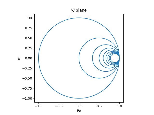
We are able to say somewhat extra. All strains comprise the purpose ∞, and f(∞) = 1, so the picture of each vertical line within the z airplane is a circle within the w airplane, contained in the unit circle and tangent to the unit circle at w = 1. (Tossing round ∞ is a bit casual, however it’s straightforward to make rigorous.)
The vertical strains within the z airplane
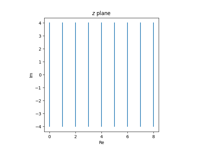
map to tangent circles within the w airplane.
Pictures of horizontal strains
Subsequent, let’s take into consideration horizontal strains within the z airplane, strains with fixed imaginary half. The picture of those strains is both a line or a circle. Which is it? The picture of a line is a line if it accommodates ∞, in any other case it’s a circle. Now f(z) = ∞ if and provided that z = −1, and so the picture of the true axis is a line, however the picture of each different horizontal line is a circle.
Since f(∞) = 1, the picture of each horizontal line passes by 1, simply as the photographs of all of the vertical strains passes by 1.
Since horizontal strains lengthen previous the suitable half-plane, the picture circles lengthen previous the unit circle. The a part of the road with constructive actual half will get mapped contained in the unit circle, and the a part of the road with detrimental actual half will get mapped exterior the unit circle. Specifically, the picture of the constructive actual axis is the interval [−1, 1].
Möbius transformations are conformal maps, and they also protect angles of intersection. Since horizontal strains are perpendicular to vertical strains, the circles which can be the photographs of the horizontal strains meet the circles which can be the photographs of vertical strains at proper angles.
The horizontal rays within the z airplane
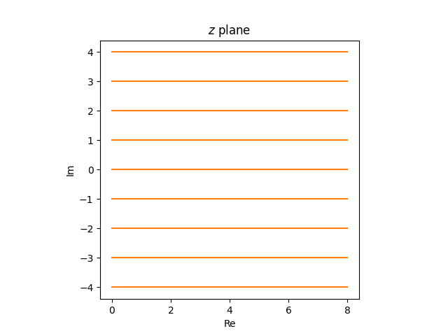
turn out to be partial circles within the w airplane.
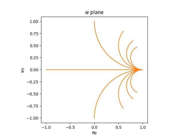
If we have been to have a look at horizontal strains reasonably than rays, i.e. if we prolonged the strains into the left half-plane, the photographs within the w airplane could be full circles.
Now let’s put our photos collectively. The grid
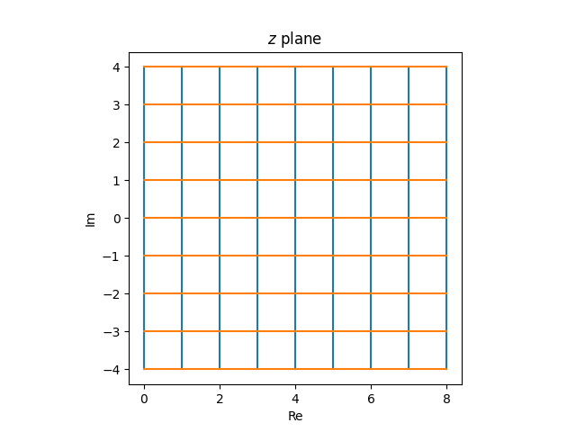
within the z airplane turns into the next within the w airplane.
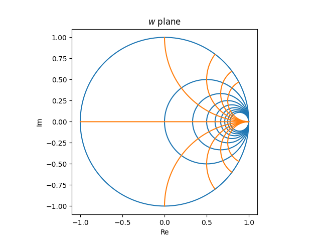
An evenly spaced grid within the z airplane turns into a really inconsistently spaced graph within the w airplane. Issues are crowded on the suitable hand aspect and sparse on the left. A useable Smith chart must be roughly evenly crammed in, which implies it must be the picture of an inconsistently crammed in grid within the z airplane. For instance, you’d want extra vertical strains within the z airplane with small actual values than with giant actual values.